VW Passat (B3) 1993 Cooling Fan Control Module Input/Output listing

| Module connector/ terminal |
Description |
| T4/1 | Power out to Coolant Fan V7 - HI speed |
| T4/2 | Power out to Coolant Fan V7 - MED speed |
| T4/3 | Power in from J32 A/C Relay and fuse S19, and F18 Coolant Fan Control Thermal Switch Terminal 2 |
| T4/4 | Power in from Battery positive |
| T8e/1 | Power out to J206 Fuel Pump After Run Control Module |
| T8e/2 | Input signal for MED speed Coolant Fan operation from F18 Coolant Fan Control Thermal Switch and/or F129 A/C Pressure Switch |
| T8e/3 | Input signal for HI speed Coolant Fan operation from F165 Third Speed Coolant Fan Thermal Switch |
| T8e/4 | Power in from fuse S13 |
| T8e/5 | Power out to N25 A/C Compressor Clutch |
| T8e/6 | Input signal from E33 A/C Evaporator Temperature Switch (anti-icing) and J44 A/C Clutch Relay |
| T8e/7 | Ground connection 193 in wiring harness |
| T8e/8 | Power out to F87 After Run Coolant Fan Control Thermal Switch |
VW Passat (B3) 1993 Radiator Cooling Fan operation
| Fan speed | Description |
| LOW | Operation is by F18 Coolant Fan Control Thermal Switch Terminal 2 at approximately 95°C or when A/C is switched on through J32 A/C Relay. Operation is independent of J293 Coolant Fan Control Module. |
| MED | Operation is by F18 Coolant Fan Control Thermal Switch Terminal 1 at approximately 102°C and/or F129 A/C Pressure Switch at A/C high side pressure of approximately 15 Bar (221 psi). Operation is controlled by J293 Coolant Fan Control Module. |
| HIGH | Operation is only by F165 Third Speed Coolant Fan Thermal Switch at approximately 119°C. Operation is controlled by J293 Coolant Fan Control Module. High speed fan operation occurs at near overheat conditions only. Note that the A/C Compressor clutch will also disengage at approximately 112°C through F163 A/C Cut-Out Thermal Switch. |
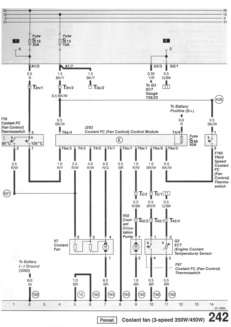
VW Passat (B3) 1993 Cooling Fan Wiring Diagram
| Description | Current track |
| Coolant Circulation Pump, V50 | 9 |
| Coolant Fan, V7 | 5-7 |
| Coolant FC (Fan Control) Control Module J293 | 4-12 |
| Coolant FC (Fan Control) Thermoswitch, F18 | 1-3 |
| Coolant FC (Fan Control) Thermoswitch F87 | 10 |
| ECT (Engine Coolant Temperature) Sensor, G2 | 11 |
| Third Speed Coolant Fan Control Thermoswitch, F165 | 14 |
| Wire connectors | |
| T2 - | double, behind relay panel |
| T2n - | double, behind relay panel |
| T2p - | double, behind relay panel |
| T4 - | four point, on Coolant FC (Fan Control) Control Module |
| T8e - | eight point, on Coolant FC (Fan Control) Control Module |
| T28 - | twenty-eight point, on Instrument Cluster |
| T42 - | fourty-two point, on Cylinder Head, left |
| Welded wiring harness points | |
| K21 - | wire connection -1-, in coolant fan wiring harness |
| K28 - | plus connection (15), in coolant fan wiring harness |
| Ground connections | |
| 15 - | ground connection, on cylinder-head |
| 182 - | ground connection -1-, in engine compartment wiring harness |
| 193 - | ground connection -1-, in coolant fan wiring harness |
 |
![[B] Bentley Publishers](http://assets1.bentleypublishers.com/images/bentley-logos/bp-banner-234x60-bookblue.jpg)